Introduction
Untested low voltage cables are one of the most common — and most overlooked — sources of network downtime, equipment failure, and compliance headaches in commercial buildings. A cable run that looks fine from the outside can harbor damaged insulation, a mis-terminated connector, or a performance gap that only shows up when you switch on a new phone system or wireless access point.
This guide covers low voltage cable testing and inspection for two overlapping categories: data and telecom cabling (Cat5e, Cat6, Cat6A, fiber optic) and power distribution cables rated 600V or below. Both run through virtually every commercial facility, and both fail quietly — until the cost becomes impossible to ignore.
Whether you're commissioning a new installation or preparing for a technology upgrade, this guide covers what testing actually involves, which standards apply, and what a thorough inspection looks like from start to finish.
Key Takeaways
- Low voltage cables support every critical system in a commercial building — untested cables can fail inspections or cause unexpected network outages
- Testing covers visual inspection, insulation resistance, continuity, connection integrity, and cable certification
- Standards like ANSI/NETA ATS-2025 and TIA-568.2-E define what "passing" means; testing without referencing them produces unreliable results
- New installations need acceptance testing; existing systems need periodic maintenance testing — both matter
- A qualified contractor ensures tests are executed, documented, and interpreted to a defensible standard
What Is Low Voltage Cable Testing and Inspection?
Low voltage cables, for the purposes of this guide, are electrical cables used at 600V or below — including power distribution wiring, structured data cabling (Cat5e, Cat6, Cat6A), and fiber optic cabling found in commercial offices, data centers, healthcare facilities, and industrial environments.
Two Contexts for Testing
Testing happens at two distinct points in a cable system's life:
- Acceptance testing — performed after a new installation, before the system is energized or goes live, to confirm everything was installed correctly
- Maintenance testing — performed periodically on existing systems to catch degradation before it causes a failure
An acceptance test tells you the installation met spec on day one. Maintenance testing tells you whether it still does after years of use, environmental exposure, and physical changes to the building.
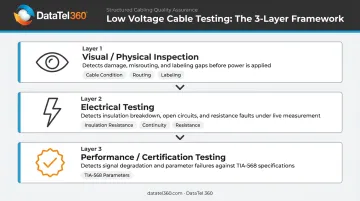
Three Layers of Testing
A complete inspection typically involves all three of these approaches:
- Visual/physical inspection — condition of cables, routing, labeling, bend radius compliance
- Electrical testing — insulation resistance, continuity, resistance measurements
- Performance/certification testing — verifying data cabling meets TIA-568 parameters using a calibrated cable certifier
Each layer catches failures the others miss. A cable can pass electrical tests and still fail certification, or pass visual inspection while harboring degraded insulation that only a megohmmeter will detect.
Why Low Voltage Cable Testing Matters for Your Business
Safety and Compliance
Damaged insulation, improper terminations, and overloaded conductors in low voltage systems can cause electrical hazards, equipment damage, and code violations. Two standards define the professional baseline for commercial facilities:
- NFPA 70B-2026 (Standard for Electrical Equipment Maintenance) — covers preventive maintenance for electrical, electronic, and communication systems
- ANSI/NETA ATS-2025 — sets acceptance testing requirements for cable systems before initial energization
Non-compliance isn't just a paperwork problem — inspectors and insurers treat these standards as enforceable expectations.
The Financial Exposure
The numbers make the case for proactive testing plainly. According to ITIC's 2024 Hourly Cost of Downtime survey of more than 1,000 firms, over 90% of midsize and large enterprises estimated average downtime costs above $300,000 per hour. Among enterprises with more than 1,000 employees, 97% reported average hourly costs exceeding $100,000.
Separately, Uptime Institute's 2025 outage analysis found that 54% of significant outages cost over $100,000, with 20% exceeding $1 million per incident.
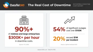
Faulty cabling is a known contributor to infrastructure failures. Proactive testing isn't a compliance checkbox — it's cost avoidance.
Infrastructure Readiness for Technology Upgrades
Businesses planning VoIP deployments, enterprise WiFi rollouts, IP security cameras, or cloud connectivity upgrades are frequently surprised to find their existing cabling doesn't meet current performance requirements. Cat5e runs that handled voice traffic without issue may fail insertion loss or crosstalk tests under modern application loads.
Testing before a technology investment answers the question that matters most: can this infrastructure actually support what we're about to put on it?
Types of Low Voltage Cable Tests and Inspections
Visual Inspection
A visual inspection covers the physical condition of the installation before any instruments come out. Inspectors walk all cable routes and check:
- Jacket and insulation condition along exposed runs (cuts, kinks, crush marks)
- Correct cable types and sizes matching project drawings and specifications
- Proper labeling and route documentation
- Bend radius compliance at corners and pulls
- Cable management integrity and support spacing
- Termination points matching the single-line diagram
Comparing installed cable against drawings and specifications is the logical first step. Errors caught here cost far less to fix than after energization.
Insulation Resistance Testing
Insulation resistance (IR) testing uses a megohmmeter to apply a controlled DC voltage to each conductor with respect to ground and adjacent conductors. The test measures how effectively the insulation resists leakage current.
Healthy insulation produces high megohm readings. Damaged, wet, or heat-degraded insulation allows more leakage and produces low readings.
Standard test voltages and minimum acceptable thresholds exist within ANSI/NETA ATS-2025, though specific values in the licensed standard should be verified directly. Moisture, heat damage, and physical installation damage are the most common causes of low readings.
Continuity and Phasing Tests
Continuity testing verifies that each conductor completes the correct circuit path end-to-end without opens or mis-connections. Phasing errors — wrong conductor-to-terminal assignments — can cause equipment malfunction or electrical faults the moment a system is first energized.
This test is critical before commissioning. A cable that looks correct at both ends can still have crossed conductors internally.
Connection and Termination Inspection
High-resistance connections are a well-documented failure point in electrical systems. Inspectors use several methods to catch problems before they cause overheating or failure:
- Low-resistance ohmmeters and torque wrenches — verify connections meet ANSI/NETA ATS-2025 bolt torque guidance
- Infrared (thermographic) surveys — identify hot connections on energized systems before they fail
- Compression connector checks — confirm proper connector rating for the cable size and correct indentation count
Cable Certification Testing (Structured Cabling)
For data and telecom cabling, certification testing uses a dedicated cable certifier (such as a Fluke DSX series analyzer) to verify that installed Cat6, Cat6A, or fiber runs meet the performance parameters defined in TIA-568.2-E, the current copper standard published November 2024.
A full certification suite covers:
| Test | What It Detects |
|---|---|
| Wire map | Opens, shorts, reversals, crossed pairs, split pairs |
| Length | Installed link length vs. standard limits |
| Insertion loss | Signal attenuation through the link |
| NEXT / PS NEXT | Near-end pair-to-pair and power-sum crosstalk |
| Return loss | Reflections from impedance discontinuities |
| Propagation delay / delay skew | Transit time and pair-to-pair timing differences |
| ACR-F / PS ACR-F | Far-end crosstalk performance relative to attenuation |
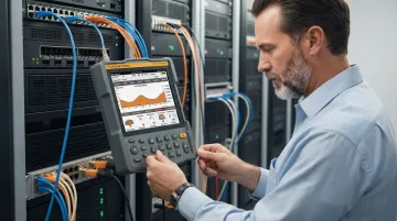
Results are documented in a pass/fail report for every individual run. That report is the client's proof that the installed cabling meets the specified performance standard.
Step-by-Step Low Voltage Cable Inspection Process
This process applies to a pre-energization acceptance inspection of newly installed low voltage cable systems. Follow the sequence as written — skipping steps or reordering them produces unreliable results that can mask real problems before energization.
Step 1 — Review Drawings and Specifications
Before touching any cable, compare the installed cable types, sizes, conductor counts, insulation ratings, and routing against project drawings. Flag all discrepancies on the test sheet. Wrong cable grade, missing runs, and incorrect routing are less costly to correct now than after energization.
Step 2 — Perform Visual and Physical Inspection
Walk all cable routes and document the condition of each section. Key checkpoints include:
- Inspect exposed jacket and insulation for cuts, crushing, or abrasion
- Verify labeling accuracy against the as-built drawings
- Confirm cables are properly supported and routed away from EMI sources
- Check that connection points match the single-line diagram
Step 3 — Inspect Connections and Terminations
Test all bolted connections with a low-resistance ohmmeter. Flag any reading more than 50% higher than comparable connections on the same circuit — that gap typically points to a loose or corroded joint requiring investigation. Check compression connectors for proper indentation depth.
For structured cabling, inspect patch panel and outlet terminations for correct wire-map and workmanship quality.
Step 4 — Perform Insulation Resistance Testing
Apply the appropriate DC test voltage to each conductor and record readings. Minimum acceptable thresholds vary by cable type — refer to ANSI/NETA ATS-2025 or the manufacturer's specifications. Values below threshold indicate compromised insulation that must be investigated and repaired before energizing.
The most common culprits are:
- Moisture intrusion at exposed termination points
- Heat damage from improper routing near high-temperature equipment
- Physical damage from installation (pinched conduit, staple penetrations)
Step 5 — Perform Continuity and Resistance Tests
Verify correct end-to-end conductor connections and phasing using a continuity tester. For parallel conductor installations, measure each cable individually with a low-resistance ohmmeter. Unequal resistance between parallel cables indicates a problem with one conductor or its connections.
Step 6 — Run Cable Certification Testing (Structured Cabling)
Execute a full TIA-568 certification test suite on every installed data or telecom link and document pass/fail results for each run. Address failures before issuing the final certification report. The three most common causes are poor termination technique, excessive pair untwisting at termination points, and physical cable damage during pulling.
How DataTel 360 Can Help
DataTel 360 has been installing, inspecting, and certifying low voltage cabling infrastructure for commercial clients across Atlanta, Georgia, and the Southeast since 1998. Their team handles the full scope — from design through post-installation testing — and delivers certified documentation that proves every run meets performance standards.
What's Included on Every Project
- Fluke-certified copper testing with pass/fail results documented per TIA standards
- OTDR-tested fiber for single-mode and multimode installations
- Labeled patch panels and cable drops matched to as-built drawings
- PDF certification reports for client records, IT team handoff, or compliance review
Because DataTel 360 handles design, installation, and testing under one engagement, there's no gap in accountability. If a cable run fails certification, one contractor owns the fix — no finger-pointing between vendors. Their 24/7 emergency support means a field technician gets dispatched when a fault surfaces after hours, not just a help desk callback.
Testing services also apply to existing infrastructure. Businesses that have never had their cabling formally certified — or are evaluating whether their current plant can support a VoIP migration, enterprise WiFi rollout, or IP camera deployment — can engage DataTel 360 for a baseline assessment.
Ready to schedule an assessment or discuss an upcoming installation? Contact DataTel 360 at 770-441-9999 or sales@datatel360.com.
Frequently Asked Questions
What is the standard for VLF cable testing?
VLF (Very Low Frequency) cable testing is governed by IEEE 400.2-2024, which covers field testing of shielded power cable systems rated 5 kV–69 kV at frequencies below 1 Hz. This standard does not apply to the 600V-and-below power or structured cabling systems covered in this guide; those fall under ANSI/NETA ATS-2025.
What is NFPA 70E for low-voltage?
NFPA 70E-2027 is the Standard for Electrical Safety in the Workplace. It establishes safe work practices, PPE requirements, and hazard boundaries for energized electrical work, including low voltage systems. Worker safety is its focus — testing and inspection procedures fall under ANSI/NETA ATS-2025.
How often should low voltage cables be tested and inspected?
Newly installed cables should be acceptance-tested before energization. For ongoing maintenance, NFPA 70B-2026 and ANSI/NETA MTS-2023 describe frequency as reliability-, condition-, and criticality-based rather than a fixed universal interval. Testing is typically triggered by performance issues, physical changes to the facility, or technology upgrade planning.
What is insulation resistance testing for low voltage cables?
IR testing applies a controlled DC voltage across cable insulation using a megohmmeter and measures how much current leaks through. Healthy insulation resists current and produces high megohm readings. Damaged, wet, or degraded insulation allows more leakage and produces low readings — indicating a problem that must be addressed before energizing the circuit.
What are the signs that low voltage cables need to be replaced?
Watch for these warning signs:
- Visibly damaged jackets or insulation
- Persistent network problems (slow speeds, dropped connections, intermittent outages)
- Insulation resistance readings below acceptable thresholds
- Failed cable certification tests
- Cables more than 20–25 years old that were never upgraded
Any of these warrant professional evaluation.
Do I need a certified technician to test low voltage cables?
Basic continuity checks can be done with simple testers. Proper acceptance testing and cable certification require calibrated equipment and technicians trained in ANSI/NETA ATS-2025 procedures and TIA-568.2-E standards — ensuring results are accurate, fully documented, and compliant.